Richards PIC Blog

Icon

Just another WordPress.com site

Very Basic Code for 2nd order IIR Filter in ‘C’

This code shows an IIR 2nd order section.

 H(z)=\frac{b_0+b_2z^{-2}}{1+a_1z^{-1}+a_2z^{-2}} 

The numerator coefficients are b=[1 0 -1];

The Denominator Coeffs are a=[1 -2rcos(\theta) r^2]; r=.8; th=pi/3;

For implementation in integer arithmetic in the PIC thte coeffs become:

b=[127 0 -128];    a=[ 127 -110 104];

The code is given followed by output from the WATCH table, which shows the response to an impulse input magnitude 50.

Then a MATLAB simulation is presented which gives the exact same integer values for the example.

Code:

 //
// Example C code for 2nd order IIR filter
//
// RGH 2012  richard.hayes@dit.ie

#include <p18f4620.h>

void main(void)
{
int yint;    // temp variable for 16 bit multiply result
char b0=127, b1=0, b2=-128, a1=-111, a2=82;
char x=50, x1=0, x2=0, y=0, y1=0, y2=0;

int bit_shift = 7;
int dc_shift = 128;

int voltage;
char datain[13]={128+50,128,128,128,128,128,128,128,128,128,128,128,128};
char dataout[13];

int i=0;

// Operating Loop
//x=50;
//i=0;
while (i<12)
{
x=datain[i]-dc_shift;    // Remove DC level from a/d i/p
//Implement the filter and crudely update the 'past' input and output x and y values
yint = (int)b0*x+(int)b1*x1+(int)b2*x2-(int)a1*y1-(int)a2*y2;
y=(char)(yint>>bit_shift);  //  8- bit result from filter. Note type casting
y2 = y1;
y1 = y;
x2 = x1;
x1 = x;
dataout[i]=y;    // Save output; this will be output to D/A
x=0;
i=i+1;

}
}

WATCH TABLE variable dataout

Update    Symbol Name       Hex    Decimal      Binary

dataout
[0]                     0x31      49          00110001
[1]                     0x2A      42          00101010
[2]                     0xD3     -45          11010011
[3]                     0xBE     -66          10111110
[4]                     0xE3     -29          11100011
[5]                     0x11      17          00010001
[6]                     0x21      33          00100001
[7]                     0x11      17          00010001
[8]                     0xF9      -7          11111001
[9]                     0xEF     -17          11101111
[10]                    0xF5     -11          11110101
[11]                    0x01       1          00000001
[12]                    0x00       0          00000000
b0                      0x7F     127          01111111

Now compare these results with the output from the following MATLAB programme:

% Simulation of integer operation of IIR filter
% The filter is implemented in 'C' for the PIC18
% The aim is to 'exactly match the integer behaviour
% of the microcontroller
clear all
b0=127; b1=0; b2=-127; a1=-111; a2=82;
x1=0; x2=0;  y1=0; y2=0;
x=50;
i=0;
for i=0:20
yint(i+1) = b0*x + b1*x1 + b2*x2  - a1*y1 - a2*y2    ;
y(i+1)=floor(yint(i+1)/(128));
y2 = y1;y1 = y(i+1);    x2 = x1;x1 = x;
x=0;
i=i+1;
%pause
end
i=0:20;
subplot(2,1,1);stem(i,y)
subplot(2,1,2);stem(i,yint)

MATLAB Output:
49,42,-45,-66,-29,17,33,17,-7,-17,-11,1,7,5,-1,-5,-4,-1,1,1,0,…

Filed under: Digital Filters,

RoboSumo Timer

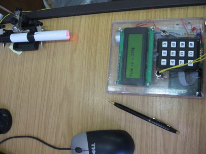
It was decided to develop an electronic timer since the reported robot speeds during the run up to the race to the wall were getting fast. Pic shows result of work since last friday (5 days ago)

RoboSumo Timer

 //
// PIC18F4620 template program
// Written by Ted Burke (ted.burke@dit.ie)
// Last update 30-1-2012
//

#include <p18f4620.h>
#include <usart.h>
#include <sw_uart.h>
#include <delays.h>
#include <stdio.h>

#pragma config OSC = INTIO67
#pragma config MCLRE = OFF
#pragma config WDT = OFF
#pragma config LVP = OFF

// Function prototypes

void setup(void);
unsigned int read_analog_channel(unsigned int);
void display(int);

void main(void)
{
int state = 1;
int light;
int on_threshold=900;
int off_threshold=900;
int counter = 0;
int LED_counter = 0;
int dead_time_counter = 0;

// Configure the PIC
setup();

display(counter);

while(1)
{
// 1ms delay
Delay10TCYx(174);

// Read inputs
light = read_analog_channel(0);

// Implement logic for current state
if (state == 1)
{
// Waiting for robot to break beam at start
if (light > on_threshold)
{
counter = 0;
state = 2;
}
}
else if (state == 2)
{
// Waiting for robot to unbreak beam at start
counter++;
// Blink LED
LED_counter++;
if (LED_counter == 100)
{
LATDbits.LATD2 = 0;
}
if (LED_counter == 200)
{
LATDbits.LATD2 = 1;
LED_counter = 0;
}
if (light < off_threshold)
{
dead_time_counter = 0;
state = 3;
}
}
else if (state == 3)
{
// 500ms dead time
counter++;
// Blink LED
LED_counter++;
if (LED_counter == 100)
{
LATDbits.LATD2 = 0;
}
if (LED_counter == 200)
{
LATDbits.LATD2 = 1;
LED_counter = 0;
}
dead_time_counter++;
if (dead_time_counter >= 500) state = 4;
}

else if (state == 4)
{
// Waiting for robot to break beam at end
counter++;
// Blink LED
LED_counter++;
if (LED_counter == 100)
{
LATDbits.LATD2 = 0;
}
if (LED_counter == 200)
{
LATDbits.LATD2 = 1;
LED_counter = 0;
}
if (light > on_threshold) state = 5;
}
else if (state == 5)
{
// Waiting for robot to unbreak beam at end
counter++;
// Blink LED
LED_counter++;
if (LED_counter == 100)
{
LATDbits.LATD2 = 0;
}
if (LED_counter == 200)
{
LATDbits.LATD2 = 1;
LED_counter = 0;
}
if (light < off_threshold)
{
state = 1;
display(counter);
LATDbits.LATD2 = 0;
}

}
}
}

void setup(void)
{
// Set clock frequency (section 2 of the PIC18F4620 Data Sheet)
// Set Fosc = 8MHz, which gives Tcy = 0.5us
OSCCON = 0b01110000;

// Set up ADC (section 19 of the PIC18F4620 Data Sheet)
// Enable AN0-7 as analog inputs
ADCON1 = 0b00000111;
// Left justified result, manual acquisition time,
// AD clock source = 8 x Tosc
ADCON2 = 0b00000001;

// Set up Port B (section 9.2 of the PIC18F4620 Data Sheet)
// RB0-5 outputs, RB6-7 inputs
LATB = 0b00000000;
TRISB = 0b11000000;

// Set up Port D (section 9.4 of the PIC18F4620 Data Sheet)
// RD0-3 digital outputs, RD4-7 digital inputs
LATD = 0b00000000;
TRISD = 0b11110000;

/*    // Set up TMR2 for 10ms time to be used as timed interrupt for
// stopwatch timer. (based on ASM Ex11.2 page 345 Gaonkar)
INTCON3=0;                // Disable all INT falgs
PIR1=0;                    // Clear all internal peripheral flags
RCONbits.IPEN=1;        // Interrupt Priority Enable
INTCON2bits.TMR0IP=1;    //Set TMR0 as High Priority
INTCON = INTCON || 0b10000111;    //Set TMR0 Global Interrupt, High Priority
//         Overflow, Interrupt flag
T0CON=0b10000111;        // Enable TMR0: 16-bit, Internal clock
// prescaler 256
*/
// Set up PWM (section 15 of the PIC18F4620 Data Sheet)
CCP1CON = 0b00001100;   // PWM on CCP1
CCP2CON = 0b00001100;   // PWM on CCP2
TRISC = 0b11111001;     // CCP1, CCP2 as outputs
T2CON = 0b00000110;     // Enable TMR2 with prescale = 16
PR2 = 255;              // period = (PR2+1) * Tcy * prescale
CCPR1L = 127;           // Ch 1 duty cycle = CCPR1L / PR2
CCPR2L = 127;           // Ch 2 duty cycle = CCPR1L / PR2

// Set up USART (section 18 of the PIC18F4620 Data Sheet)
// baud_rate = Fosc/(16*(spbrg+1))
//           = 8000000/(16*(207+1)) = 2403.846
OpenUSART(USART_TX_INT_OFF & USART_RX_INT_OFF
& USART_ASYNCH_MODE & USART_EIGHT_BIT
& USART_CONT_RX & USART_BRGH_HIGH, 51);
}

// Read voltage from the specified channel.
// This function takes approximately 35us.
unsigned int read_analog_channel(unsigned int n)
{
unsigned int voltage;

ADCON0 = n << 2;
ADCON0bits.ADON = 1;
Delay10TCYx(3); // 15us charging time
ADCON0bits.GO = 1;
while (ADCON0bits.GO); // Await result (11us approx)

// Return the result (a number between 0 and 1023)
voltage = ADRESH;
voltage = (voltage << 2) + (ADRESL >> 6);
return voltage;
}
void display(int counter)
{
int countout=0; // used for display format
int countout1=0; // Used for display format
WriteUSART(12);
WriteUSART(3);
WriteUSART(2);
WriteUSART(10);

countout1=counter/1000;
countout=counter-countout1*1000;

printf("Time is %d",countout1);
WriteUSART(46);
printf("%d",countout);
}

Filed under: Digital Filters

The 4 x 3 MAtrix keyboard

I want to focus on the various parts of the setup described previously.

The keyboard came with the LCD03 from Active Robots (http://www.robot-electronics.co.uk/htm/Lcd03tech.htm). The pins are arranged as shown

PIC pin 39 38 37 36 35 34 33
PORTBbit 6 5 4 3 2 1 0
Keypad Pin 2 3 4 5 6 7 8
  Col 2 Row 1 Col 1 Row 4 Col 3 Row 3 Row 2


The keypad is connected directly pin for pin to the 7 LSbits of PORTB and uses the internal pull-ups. Thus the columns and rows are not in a logical order.

The use of the internal pullups has to be initialised.

The keyboard function I have written is given here. Bits RB2,RB4 and RB6 are set as outputs to drive the colums. Bits RB 0,1,3,5 are set as inputs to read/scan the rows.


char keyboard(void); //Prototype

char keyboard()
{
 char newkey;
 PORTB=0b00101011;
 if(PORTB<0b00101011)
 {
 PORTB=0xff;
 PORTBbits.RB4=0;
 if(PORTBbits.RB5==0){newkey='1';return newkey;}
 if(PORTBbits.RB0==0){newkey='4';return newkey;}
 if(PORTBbits.RB1==0){newkey='7';return newkey;}
 if(PORTBbits.RB3==0){newkey='*';return newkey;}
 PORTBbits.RB6=0;
 if(PORTBbits.RB5==0){newkey='2';return newkey;}
 if(PORTBbits.RB0==0){newkey='5';return newkey;}
 if(PORTBbits.RB1==0){newkey='8';return newkey;}
 if(PORTBbits.RB3==0){newkey='0';return newkey;}
 PORTBbits.RB2=0;
 if(PORTBbits.RB5==0){newkey='3';return newkey;}
 if(PORTBbits.RB0==0){newkey='6';return newkey;}
 if(PORTBbits.RB1==0){newkey='9';return newkey;}
 if(PORTBbits.RB3==0){newkey='#';return newkey;}
 }
 else {return 0;}
}

void setup(void)
{
// Configure PORTB pins for Keypad
 INTCON2bits.RBPU=0; // turn on pull ups
 ADCON1=0b00000111;
 LATB = 0b11111111; // Set port B data latch, so that any pins that any outputs pins will be 0V initially.
 TRISB = 0b10101011; //
 PORTB=0xff;

Filed under: Digital Filters

Setup for PIC18 Human Interface examples

Overview

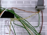
Closeup of BreadBoard

Filed under: Digital Filters

Displays and Keboards with the PIC18f

I have been developing a range of code to implement a variety of human interfaces for the PIC18f. They include:

  1. LEDS and Switches, the normal starting point
  2. A 4 character 7-segment display
  3. A 3×4 matrix keypad
  4. LCD03 , a 4 line by 20 character LCD I/^2 C UART display

This section gives the basic starting code for LEDs and Switches

//
// main.c - A simple example program for the PIC18F4620.
// This program just sets the volage on pin 19 high and
// low repeatedly to flash an LED on and off.
//
// Written by Richard Hayes - 2011
//
// Original template Written by Ted Burke - last modified 16-2-2009
//

// The following header file defines various values that are
// relevant to this chip, such as port names, etc
#include "p18f4620.h"

// The following three lines configure some global chip
// settings, such as oscillator type and clock speed.
// You probably won't need to change these at all.
#pragma config OSC = INTIO67 // Sets the oscillator mode to HS
#pragma config WDT = OFF  // Turns the watchdog timer off
#pragma config MCLRE = OFF  // Turns low voltage programming off
#pragma config LVP = OFF

// This is a function prototype for a function that is defined below.
void configure_pins(void);

// This is the "main" function -
void main(void)
{
// Declare variables
int n;

// Configure which pins are inputs and which are outputs
configure_pins();

while(1)
{
if(PORTBbits.RB0==0)
{
LATDbits.LATD0=1;
for(n=0;n<16000;n++);
LATDbits.LATD0=0;
for(n=0;n<16000;n++);
}
//LATDbits.LATD0=!PORTBbits.RB0;
else{
LATDbits.LATD0=1;
for(n=0;n<1000;n++);
LATDbits.LATD0=0;
for(n=0;n<1000;n++);
}
/*LATDbits.LATD0=1;
for(n=0;n<8000;n++);
LATDbits.LATD0=0;
LATDbits.LATD1=1;
for(n=0;n<8000;n++);
LATDbits.LATD1=0;
LATDbits.LATD2=1;
for(n=0;n<20000;n++);
LATDbits.LATD2=0;*/
}
}

void configure_pins()
{
// Configure port B digital outputs
ADCON1=0b00000111;
PORTB = 0; // Set port B data latch, so that any pins that any outputs pins will be 0V initially.
TRISB = 0b11111111; //
INTCON2bits.RBPU=0; // turn on pull ups
// Configure port D digital i/o
// Inputs:  27, 28, 29 and 30 (RD4, RD5, RD6 and RD7)
// Outputs: 19, 20, 21 and 22 (RD0, RD1, RD2 and RD3)
LATD = 0; // Set port D data latch, so that any pins that any outputs pins will be 0V initially.
TRISD = 0b11110000; // This binary value sets pins RD4-7 as inputs and RD0-3 as outputs.
}


 2. Code for 4 character 7-segment dispaly integrated with 4×3 MAtrix keypad.

//
// main.c -
//
// Written by Ted Burke and Richard Hayes - last modified April 2011
//

// The following header file defines various values that are
// relevant to this chip, such as port names, etc
#include "p18f4620.h"

// The following lines configure some global chip
// settings, such as oscillator type and clock speed.
// You probably won't need to change these at all.
#pragma config OSC = INTIO67 // Sets the oscillator mode to HS
#pragma config WDT = OFF  // Turns the watchdog timer off
#pragma config MCLRE = OFF  // Turns low voltage programming off
#pragma config LVP = OFF

void configure_pins(void);
int keyboard();

void main(void)
{
// Declare variables
int n;
int diskey;
int display=0;
configure_pins();
while(1)

{
LATCbits.LATC3=0;
diskey=keyboard();
//if(display!=newkey){display=newkey;}
LATD=diskey;
}
}
void configure_pins()
{
// Configure port B digital outputs
INTCON2bits.RBPU=0; // turn on pull ups
ADCON1=0b00000111;
LATB = 0b11111111; // Set port B data latch, so that any pins that any outputs pins will be 0V initially.
TRISB = 0b10101011; //
PORTB=0xff;

TRISC = 0b11110000; // This binary value sets pins RD4-7 as inputs and RD0-3 as outputs.
LATC = 0xf7; // Set port C data latch, so that any pins that any outputs pins will be 0V initially.

TRISD = 0b00000000; // This binary value sets pins RD4-7 as inputs and RD0-3 as outputs.
LATD = 0x00; // Set port D data latch, so that any pins that any outputs pins will be 0V initially.
LATC = 0xff; // Set port C data latch, so that any pins that any outputs pins will be 0V initially.
}
//int keyboard(int display)
int keyboard()
{
int newkey;
if(PORTB<0xff)
{
PORTB=0xff;
PORTBbits.RB2=0;
if(PORTBbits.RB5==0){newkey=0x4f;return newkey;}
if(PORTBbits.RB0==0){newkey=0x7d;return newkey;}
if(PORTBbits.RB1==0){newkey=0x67;return newkey;}
if(PORTBbits.RB3==0){newkey=0x76;return newkey;}
PORTBbits.RB6=0;
if(PORTBbits.RB5==0){newkey=0x5b;return newkey;}
if(PORTBbits.RB0==0){newkey=0x6d;return newkey;}
if(PORTBbits.RB1==0){newkey=0x7f;return newkey;}
if(PORTBbits.RB3==0){newkey=0x3f;return newkey;}
PORTBbits.RB4=0;
if(PORTBbits.RB5==0){newkey=0x06;return newkey;}
if(PORTBbits.RB0==0){newkey=0x66;return newkey;}
if(PORTBbits.RB1==0){newkey=0x07;return newkey;}
if(PORTBbits.RB3==0){newkey=0x70;return newkey;}
}
else{newkey=newkey;return 0x52;}
}

AND Finally Integration of the 4x3 keypad with the LCD Display:


///////////////////////////////////////////////////////////////////////
//
//     PIC18F4620 - LCD03 example</code></code>

//     Integrating LCD03 with 4x3 keyboard interfaced through Port B
//
//     Richard Hayes  April 2011
//
//
///////////////////////////////////////////////////////////////////////

#include "p18f4620.h"
#include "stdio.h"

// global chip settings, such as oscillator type and clock speed.

#pragma config OSC = INTIO67 // Sets the oscillator mode to HS
#pragma config WDT = OFF  // Turns the watchdog timer off
#pragma config MCLRE = OFF  // Turns low voltage programming off
#pragma config LVP = OFF

void clrscn(void);    // prototypes
void cursoroff(void);
void carretrn(void);
void cursor(char pos);
void print(char *p);
void printchar(char onechar);
void setup(void);
char keyboard(void);
void printDecimal( int dec);
void printHex(unsigned int val);

char s[21];
char keynum;

int n;
int i;
char diskey;
int oldkey;

void main(void)
{
for(i=0;i<20;i++)
{s[i]=0;}

setup();     // sets up the PIC16F877 I2C port
clrscn();     // clears the LCD03 disply
cursor(1);     // sets cursor to top left of LCD03
// carretrn();

s[0]=0x35;
s[1]=0x36;
s[2]=0x37;
s[3]=0x38;
s[4]=0x39;
s[5]=0x30;
print(s);
printDecimal(-31234);
carretrn();
printHex(0xabd4);printchar(0x20);printDecimal(31234);

/* sprintf(s,"Hello World");
print(s);*/
// carretrn();

while(1)
{
while(keyboard()==0);
keynum=keyboard();
while(keyboard()!=0);
printchar(keynum);

}
}
void clrscn(void)
{
SSPCON2bits.SEN = 1;     // send start bit
while(SSPCON2bits.SEN);     // and wait for it to clear

PIR1bits.SSPIF = 0;
SSPBUF = 0xc6;    // LCD02 I2C address
while(!PIR1bits.SSPIF);    // wait for interrupt
PIR1bits.SSPIF = 0;     // then clear it.

SSPBUF = 0;     // address of register to write to
while(!PIR1bits.SSPIF);    //
PIR1bits.SSPIF = 0;     //

SSPBUF = 12;    // clear screen
while(!PIR1bits.SSPIF);    //
PIR1bits.SSPIF = 0;     //

SSPBUF = 6;     // cursor off
while(!PIR1bits.SSPIF);    //
PIR1bits.SSPIF = 0;     //

SSPCON2bits.PEN = 1;     // send stop bit
while(SSPCON2bits.PEN);     //
}

void cursoroff(void)
{
SSPCON2bits.SEN = 1;     // send start bit
while(SSPCON2bits.SEN);     // and wait for it to clear

PIR1bits.SSPIF = 0;
SSPBUF = 0xc6;    // LCD02 I2C address
while(!PIR1bits.SSPIF);    // wait for interrupt
PIR1bits.SSPIF = 0;     // then clear it.

SSPBUF = 0;     // address of register to write to
while(!PIR1bits.SSPIF);    //
PIR1bits.SSPIF = 0;     //

SSPBUF = 4;     // cursor off
while(!PIR1bits.SSPIF);    //
PIR1bits.SSPIF = 0;     //

SSPCON2bits.PEN = 1;     // send stop bit
while(SSPCON2bits.PEN);     //
}

void carretrn(void)
{
SSPCON2bits.SEN = 1;     // send start bit
while(SSPCON2bits.SEN);     // and wait for it to clear

PIR1bits.SSPIF = 0;
SSPBUF = 0xc6;    // LCD02 I2C address
while(!PIR1bits.SSPIF);    // wait for interrupt
PIR1bits.SSPIF = 0;     // then clear it.

SSPBUF = 0;     // address of register to write to
while(!PIR1bits.SSPIF);    //
PIR1bits.SSPIF = 0;     //

SSPBUF = 13;    // clear screen
while(!PIR1bits.SSPIF);    //
PIR1bits.SSPIF = 0;     //

SSPBUF = 6;     // cursor to BLINK
while(!PIR1bits.SSPIF);    //
PIR1bits.SSPIF = 0;     //


SSPCON2bits.PEN = 1;     // send stop bit
while(SSPCON2bits.PEN);     //
}


void cursor(char pos)
{
SSPCON2bits.SEN = 1;     // send start bit
while(SSPCON2bits.SEN);     // and wait for it to clear

PIR1bits.SSPIF = 0;
SSPBUF = 0xc6;    // LCD02 I2C address
while(!PIR1bits.SSPIF);    // wait for interrupt
PIR1bits.SSPIF = 0;     // then clear it.

SSPBUF = 0;     // address of register to write to
while(!PIR1bits.SSPIF);    //
PIR1bits.SSPIF = 0;     //

SSPBUF = 2;     // set cursor
while(!PIR1bits.SSPIF);    //
PIR1bits.SSPIF = 0;     //
SSPBUF = pos;    //
while(!PIR1bits.SSPIF);    //
PIR1bits.SSPIF = 0;     //

SSPCON2bits.PEN = 1;     // send stop bit
while(SSPCON2bits.PEN);     //
}


void print(char *p)
{
SSPCON2bits.SEN = 1;     // send start bit
while(SSPCON2bits.SEN);     // and wait for it to clear

PIR1bits.SSPIF = 0;
SSPBUF = 0xc6;    // LCD02 I2C address
while(!PIR1bits.SSPIF);    // wait for interrupt
PIR1bits.SSPIF = 0;     // then clear it.

SSPBUF = 0;     // address of register to write to
while(!PIR1bits.SSPIF);    //
PIR1bits.SSPIF = 0;     //

while(*p) {
SSPBUF = *p++;   // write the data
while(!PIR1bits.SSPIF);   //
PIR1bits.SSPIF = 0;    //
}

SSPCON2bits.PEN = 1;     // send stop bit
while(SSPCON2bits.PEN);     //
}
void printchar(char onechar)
{
SSPCON2bits.SEN = 1;     // send start bit
while(SSPCON2bits.SEN);     // and wait for it to clear

PIR1bits.SSPIF = 0;
SSPBUF = 0xc6;    // LCD02 I2C address
while(!PIR1bits.SSPIF);    // wait for interrupt
PIR1bits.SSPIF = 0;     // then clear it.

SSPBUF = 0;     // address of register to write to
while(!PIR1bits.SSPIF);    //
PIR1bits.SSPIF = 0;     //

SSPBUF = onechar;    //
while(!PIR1bits.SSPIF);    //
PIR1bits.SSPIF = 0;     //


SSPCON2bits.PEN = 1;     // send stop bit
while(SSPCON2bits.PEN);     //
}

char HexDigit(int digitvalue) {
if (digitvalue < 10)
return(digitvalue + '0');
else
return(digitvalue + 'A' - 10);
}
void printByte(unsigned int theByte) {
char HexBuffer[3];
HexBuffer[2] = 0;
HexBuffer[1] = HexDigit(theByte & 0x000f);
theByte = theByte >> 4;
HexBuffer[0] = HexDigit(theByte & 0x000f);
print(HexBuffer);
}
void printHex(unsigned int Number) {
char HexBuffer[5];
HexBuffer[4] = 0;
HexBuffer[3] = HexDigit(Number & 0x000f);
Number = Number >> 4;
HexBuffer[2] = HexDigit(Number & 0x000f);
Number = Number >> 4;
HexBuffer[1] = HexDigit(Number & 0x000f);
Number = Number >> 4;
HexBuffer[0] = HexDigit(Number & 0x000f);
print(HexBuffer);
}
void printDecimal(int Number) {
// need to move to long int to account for
// negative 32768
char DecimalBuffer[7];
long lNumber = Number;
DecimalBuffer[6] = 0;
if (lNumber < 0) {
DecimalBuffer[0] = '-';
lNumber = -lNumber;
} else
DecimalBuffer[0] = '+';
DecimalBuffer[5] = (lNumber % 10)+'0';
lNumber = lNumber / 10;
DecimalBuffer[4] = (lNumber % 10)+'0';
lNumber = lNumber / 10;
DecimalBuffer[3] = (lNumber % 10)+'0';
lNumber = lNumber / 10;
DecimalBuffer[2] = (lNumber % 10)+'0';
lNumber = lNumber / 10;
DecimalBuffer[1] = (lNumber % 10)+'0';
print(DecimalBuffer);
}
char keyboard()
{
char newkey;
PORTB=0b00101011;
if(PORTB<0b00101011)
{
PORTB=0xff;
PORTBbits.RB4=0;
if(PORTBbits.RB5==0){newkey='1';return newkey;}
if(PORTBbits.RB0==0){newkey='4';return newkey;}
if(PORTBbits.RB1==0){newkey='7';return newkey;}
if(PORTBbits.RB3==0){newkey='*';return newkey;}
PORTBbits.RB6=0;
if(PORTBbits.RB5==0){newkey='2';return newkey;}
if(PORTBbits.RB0==0){newkey='5';return newkey;}
if(PORTBbits.RB1==0){newkey='8';return newkey;}
if(PORTBbits.RB3==0){newkey='0';return newkey;}
PORTBbits.RB2=0;
if(PORTBbits.RB5==0){newkey='3';return newkey;}
if(PORTBbits.RB0==0){newkey='6';return newkey;}
if(PORTBbits.RB1==0){newkey='9';return newkey;}
if(PORTBbits.RB3==0){newkey='#';return newkey;}
}
else {return 0;}
}
void setup(void)
{
unsigned long x;

INTCON2bits.RBPU=0; // turn on pull ups
ADCON1=0b00000111;
LATB = 0b11111111; // Set port B data latch, so that any pins that any outputs pins will be 0V initially.
TRISB = 0b10101011; //
PORTB=0xff;

// TRISC = 0b11110000; // This binary value sets pins RD4-7 as inputs and RD0-3 as outputs.
// LATC = 0xf7; // Set port C data latch, so that any pins that any outputs pins will be 0V initially.

TRISD = 0b00000000; // This binary value sets pins RD4-7 as inputs and RD0-3 as outputs.
LATD = 0x00; // Set port D data latch, so that any pins that any outputs pins will be 0V initially.
// LATC = 0xff; // Set port C data latch, so that any pins that any outputs pins will be 0V initially.

TRISC = 0xff;
PORTC = 0xff;

SSPSTAT = 0x80;
SSPCON1 = 0x38;
SSPCON2 = 0x00;
SSPADD = 10;    // SCL = 91khz with 4Mhz Osc

for(x=0; x<60000; x++);  // wait for LCD03 to initialise

}

Filed under: Digital Filters

Hello world!

Welcome to WordPress.com. After you read this, you should delete and write your own post, with a new title above. Or hit Add New on the left (of the admin dashboard) to start a fresh post.

Here are some suggestions for your first post.

  1. You can find new ideas for what to blog about by reading the Daily Post.
  2. Add PressThis to your browser. It creates a new blog post for you about any interesting  page you read on the web.
  3. Make some changes to this page, and then hit preview on the right. You can alway preview any post or edit you before you share it to the world.

Filed under: Digital Filters

Pages