Richards PIC Blog

Icon

Just another WordPress.com site

Very Basic Code for 2nd order IIR Filter in ‘C’

This code shows an IIR 2nd order section.

 H(z)=\frac{b_0+b_2z^{-2}}{1+a_1z^{-1}+a_2z^{-2}} 

The numerator coefficients are b=[1 0 -1];

The Denominator Coeffs are a=[1 -2rcos(\theta) r^2]; r=.8; th=pi/3;

For implementation in integer arithmetic in the PIC thte coeffs become:

b=[127 0 -128];    a=[ 127 -110 104];

The code is given followed by output from the WATCH table, which shows the response to an impulse input magnitude 50.

Then a MATLAB simulation is presented which gives the exact same integer values for the example.

Code:

 //
// Example C code for 2nd order IIR filter
//
// RGH 2012  richard.hayes@dit.ie

#include <p18f4620.h>

void main(void)
{
int yint;    // temp variable for 16 bit multiply result
char b0=127, b1=0, b2=-128, a1=-111, a2=82;
char x=50, x1=0, x2=0, y=0, y1=0, y2=0;

int bit_shift = 7;
int dc_shift = 128;

int voltage;
char datain[13]={128+50,128,128,128,128,128,128,128,128,128,128,128,128};
char dataout[13];

int i=0;

// Operating Loop
//x=50;
//i=0;
while (i<12)
{
x=datain[i]-dc_shift;    // Remove DC level from a/d i/p
//Implement the filter and crudely update the 'past' input and output x and y values
yint = (int)b0*x+(int)b1*x1+(int)b2*x2-(int)a1*y1-(int)a2*y2;
y=(char)(yint>>bit_shift);  //  8- bit result from filter. Note type casting
y2 = y1;
y1 = y;
x2 = x1;
x1 = x;
dataout[i]=y;    // Save output; this will be output to D/A
x=0;
i=i+1;

}
}

WATCH TABLE variable dataout

Update    Symbol Name       Hex    Decimal      Binary

dataout
[0]                     0x31      49          00110001
[1]                     0x2A      42          00101010
[2]                     0xD3     -45          11010011
[3]                     0xBE     -66          10111110
[4]                     0xE3     -29          11100011
[5]                     0x11      17          00010001
[6]                     0x21      33          00100001
[7]                     0x11      17          00010001
[8]                     0xF9      -7          11111001
[9]                     0xEF     -17          11101111
[10]                    0xF5     -11          11110101
[11]                    0x01       1          00000001
[12]                    0x00       0          00000000
b0                      0x7F     127          01111111

Now compare these results with the output from the following MATLAB programme:

% Simulation of integer operation of IIR filter
% The filter is implemented in 'C' for the PIC18
% The aim is to 'exactly match the integer behaviour
% of the microcontroller
clear all
b0=127; b1=0; b2=-127; a1=-111; a2=82;
x1=0; x2=0;  y1=0; y2=0;
x=50;
i=0;
for i=0:20
yint(i+1) = b0*x + b1*x1 + b2*x2  - a1*y1 - a2*y2    ;
y(i+1)=floor(yint(i+1)/(128));
y2 = y1;y1 = y(i+1);    x2 = x1;x1 = x;
x=0;
i=i+1;
%pause
end
i=0:20;
subplot(2,1,1);stem(i,y)
subplot(2,1,2);stem(i,yint)

MATLAB Output:
49,42,-45,-66,-29,17,33,17,-7,-17,-11,1,7,5,-1,-5,-4,-1,1,1,0,…

Filed under: Digital Filters,

4 character 7-segment common cathode display

Basic decode for 4 character 7-segment common cathode display. 57-1093, anodes connected to Port D and segments controlled from port C0-C3.

//
// main.c - A simple example 7-segment LED control program.
// This program use a Table Lookup approach to decode a 7-segment LED
// multi-digit LED dsiplay.
//
// Written by Richard HAyes  - last modified 23-03-2012
//

// The following header file defines various values that are
// relevant to this chip, such as port names, etc
#include "p18f4620.h"

// Configure some global chip settings, such as oscillator type and clock speed
//
#pragma config OSC = INTIO67    // Sets the oscillator mode to HS
#pragma config WDT = OFF        // Turns the watchdog timer off
#pragma config MCLRE = OFF        // Turns low voltage programming off

// Configure Pins.
void configure_pins(void);

void main(void)
{
// Declare variables
int n;
int delay = 8;
char    LUT[10]={0x3f,0x06,0x5b,0x4f,0x66,0x6d,0x7d,0x07,0x7f,0x67};
int    number[4]={1,2,3,5};
int    N=3;
int    M=4;
int    L=8;
int    K=1;
LATC=0x0f;

// Configure which pins are inputs and which are outputs
configure_pins();

while(1)
{
LATC=0x0f;                    // All Digits off
LATD = LUT[number[0]];
LATCbits.LATC3=0;            // Most Significant Digit
for (n=0 ; n<delay ; ++n);    // delay
LATC=0x0f;                    // All Digits off
LATD = LUT[number[1]];
LATCbits.LATC2=0;            // Next Significant Digit
for (n=0 ; n<delay ; ++n);    // delay
LATC=0x0f;                    // All Digits off
LATD = LUT[number[2]];
LATCbits.LATC1=0;            // Next Significant Digit
for (n=0 ; n<delay ; ++n);    // delay
LATC=0x0f;                    // All Digits off
LATD = LUT[number[3]];
LATCbits.LATC0=0;            // Next Significant Digit
for (n=0 ; n<delay ; ++n);    // delay

/*        LATD = 0x00;                // Blank
LATC=0b00000001;            // MS Digit
LATD = LUT[L];                // Least Significant Digit
for (n=0 ; n<delay ; ++n);    // delay
LATD = 0x00;                // Blank
//        LATC=0b00000010;            // MS Digit*/

}
}

// Function to configure digital I/O pins etc.
// This fucntion only configures port D so far - later on,
// you will need to configure settings for other pins on
// the chip.
void configure_pins()
{
// Configure port C digital inputs and outputs
// Inputs:  15, 16, 17, 18 (RC0, RC1, RC2 and RC3)
// Outputs: 19, 20, 21 and 22 (RD0, RD1, RD2 and RD3)
LATC = 0; // Set port C data latch, so that any pins that any outputs pins will be 0V initially.
TRISC = 0b11110000; // This binary value sets pins C0-3 as outputs and RC4-7 as inputs.
// Configure port D digital i/o
// Outputs: 19, 20, 21 and 22 27, 28, 29 and 30(RD0, RD1, RD2, RD3,RD4, RD5, RD6 and RD7)
LATD = 0; // Set port D data latch, so that any pins that any outputs pins will be 0V initially.
TRISD = 0b00000000; // This binary value sets pins RD0-7 as outputs.
}

Filed under: Displays

RoboSumo Timer

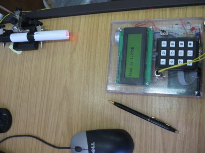
It was decided to develop an electronic timer since the reported robot speeds during the run up to the race to the wall were getting fast. Pic shows result of work since last friday (5 days ago)

RoboSumo Timer

 //
// PIC18F4620 template program
// Written by Ted Burke (ted.burke@dit.ie)
// Last update 30-1-2012
//

#include <p18f4620.h>
#include <usart.h>
#include <sw_uart.h>
#include <delays.h>
#include <stdio.h>

#pragma config OSC = INTIO67
#pragma config MCLRE = OFF
#pragma config WDT = OFF
#pragma config LVP = OFF

// Function prototypes

void setup(void);
unsigned int read_analog_channel(unsigned int);
void display(int);

void main(void)
{
int state = 1;
int light;
int on_threshold=900;
int off_threshold=900;
int counter = 0;
int LED_counter = 0;
int dead_time_counter = 0;

// Configure the PIC
setup();

display(counter);

while(1)
{
// 1ms delay
Delay10TCYx(174);

// Read inputs
light = read_analog_channel(0);

// Implement logic for current state
if (state == 1)
{
// Waiting for robot to break beam at start
if (light > on_threshold)
{
counter = 0;
state = 2;
}
}
else if (state == 2)
{
// Waiting for robot to unbreak beam at start
counter++;
// Blink LED
LED_counter++;
if (LED_counter == 100)
{
LATDbits.LATD2 = 0;
}
if (LED_counter == 200)
{
LATDbits.LATD2 = 1;
LED_counter = 0;
}
if (light < off_threshold)
{
dead_time_counter = 0;
state = 3;
}
}
else if (state == 3)
{
// 500ms dead time
counter++;
// Blink LED
LED_counter++;
if (LED_counter == 100)
{
LATDbits.LATD2 = 0;
}
if (LED_counter == 200)
{
LATDbits.LATD2 = 1;
LED_counter = 0;
}
dead_time_counter++;
if (dead_time_counter >= 500) state = 4;
}

else if (state == 4)
{
// Waiting for robot to break beam at end
counter++;
// Blink LED
LED_counter++;
if (LED_counter == 100)
{
LATDbits.LATD2 = 0;
}
if (LED_counter == 200)
{
LATDbits.LATD2 = 1;
LED_counter = 0;
}
if (light > on_threshold) state = 5;
}
else if (state == 5)
{
// Waiting for robot to unbreak beam at end
counter++;
// Blink LED
LED_counter++;
if (LED_counter == 100)
{
LATDbits.LATD2 = 0;
}
if (LED_counter == 200)
{
LATDbits.LATD2 = 1;
LED_counter = 0;
}
if (light < off_threshold)
{
state = 1;
display(counter);
LATDbits.LATD2 = 0;
}

}
}
}

void setup(void)
{
// Set clock frequency (section 2 of the PIC18F4620 Data Sheet)
// Set Fosc = 8MHz, which gives Tcy = 0.5us
OSCCON = 0b01110000;

// Set up ADC (section 19 of the PIC18F4620 Data Sheet)
// Enable AN0-7 as analog inputs
ADCON1 = 0b00000111;
// Left justified result, manual acquisition time,
// AD clock source = 8 x Tosc
ADCON2 = 0b00000001;

// Set up Port B (section 9.2 of the PIC18F4620 Data Sheet)
// RB0-5 outputs, RB6-7 inputs
LATB = 0b00000000;
TRISB = 0b11000000;

// Set up Port D (section 9.4 of the PIC18F4620 Data Sheet)
// RD0-3 digital outputs, RD4-7 digital inputs
LATD = 0b00000000;
TRISD = 0b11110000;

/*    // Set up TMR2 for 10ms time to be used as timed interrupt for
// stopwatch timer. (based on ASM Ex11.2 page 345 Gaonkar)
INTCON3=0;                // Disable all INT falgs
PIR1=0;                    // Clear all internal peripheral flags
RCONbits.IPEN=1;        // Interrupt Priority Enable
INTCON2bits.TMR0IP=1;    //Set TMR0 as High Priority
INTCON = INTCON || 0b10000111;    //Set TMR0 Global Interrupt, High Priority
//         Overflow, Interrupt flag
T0CON=0b10000111;        // Enable TMR0: 16-bit, Internal clock
// prescaler 256
*/
// Set up PWM (section 15 of the PIC18F4620 Data Sheet)
CCP1CON = 0b00001100;   // PWM on CCP1
CCP2CON = 0b00001100;   // PWM on CCP2
TRISC = 0b11111001;     // CCP1, CCP2 as outputs
T2CON = 0b00000110;     // Enable TMR2 with prescale = 16
PR2 = 255;              // period = (PR2+1) * Tcy * prescale
CCPR1L = 127;           // Ch 1 duty cycle = CCPR1L / PR2
CCPR2L = 127;           // Ch 2 duty cycle = CCPR1L / PR2

// Set up USART (section 18 of the PIC18F4620 Data Sheet)
// baud_rate = Fosc/(16*(spbrg+1))
//           = 8000000/(16*(207+1)) = 2403.846
OpenUSART(USART_TX_INT_OFF & USART_RX_INT_OFF
& USART_ASYNCH_MODE & USART_EIGHT_BIT
& USART_CONT_RX & USART_BRGH_HIGH, 51);
}

// Read voltage from the specified channel.
// This function takes approximately 35us.
unsigned int read_analog_channel(unsigned int n)
{
unsigned int voltage;

ADCON0 = n << 2;
ADCON0bits.ADON = 1;
Delay10TCYx(3); // 15us charging time
ADCON0bits.GO = 1;
while (ADCON0bits.GO); // Await result (11us approx)

// Return the result (a number between 0 and 1023)
voltage = ADRESH;
voltage = (voltage << 2) + (ADRESL >> 6);
return voltage;
}
void display(int counter)
{
int countout=0; // used for display format
int countout1=0; // Used for display format
WriteUSART(12);
WriteUSART(3);
WriteUSART(2);
WriteUSART(10);

countout1=counter/1000;
countout=counter-countout1*1000;

printf("Time is %d",countout1);
WriteUSART(46);
printf("%d",countout);
}

Filed under: Digital Filters

Pages